|
Designing a
Simple
Transistor Circuit
|
|
This may be of
interest to electric guitarists who want to become more of an anorak
about their craft!
|
|
|
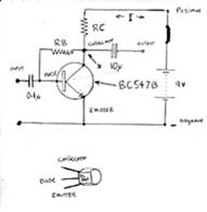
Here we will deal with a ubiquitous transistor BC547, for use in audio
frequency applications. Its the same as a BC 107 NPN, although in a plastic TO92
package for cheapness. Supply is a 9 volt PP3, bias: class A and common emitter
configuration. For simplicity let's ignore the 0.1u and 10u capacitors and consider only the
DC
conditions, its all bog-standard Ohms Law; V = R X I or R = V /I or I = V/R, and
another transistor quantity: hfe. Seen on digital multi-meters, its purpose is
to test transistors for gain amounts. Also known as Beta, hfe is the ratio of
current (I) difference between the collector and base of a transistor and the
higher this figure, the higher the gain. The required collector current depends
on the signal level that our transistor needs to work at. This could be up to
thirty milliamps (30mA) driving a 65 ohm loudspeaker in an intercom for
example. At the opposite extreme transistors used in low level pre-amp stages, may require only 100
micro-amps collector current. In fact, 100uA 30mA is the approximate usable
working current range of a BC547 although it will pass
100mA
max Ic, @ full saturation, for our purposes, more than 30mA makes it overheat, causing burns, and at less than 100uA
the gain drops below a useful level: In such circumstances wed need to select
an alternative type. We will design a one stage, single transistor amplifier,
useful as a guitar tube-driver: This will enable the instrument to push an amplifier into overdrive distortion. 1 mA
will suffice for the collector and next comes Ohms Law. In the diagram theres
an X and is the junction of collector, RB, RC and one end of the 10uF. When
working, point X should be half supply voltage: 9/2 = 4.5Vwith respect to the grounded
emitter. In practice, this could be
anywhere between 3 7 volts but half supply is ideal. The current, as
mentioned, is 1mA: same as 0.001 amps. Press ON on your calculator and enter
4.5 (half 9) then press divide - by your current which is 0.001 (1milliamp). Youll
get 4500. This is your value for RC. Youre unlikely to find a 4.5k so instead
we use 4.7k; nearest preferred value: hereon abbreviated NPV.
|
|
|
|
Determining the
value of the Base Bias Resistor.
|
|
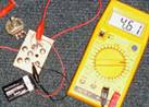
The
transistor wont do anything until a base-bias resistor is connected. Working
out RB (Resistance Base) is more difficult and you must find the hfe of your
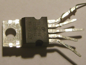
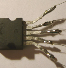
BC547. Do this with the hfe function on a multi-meter. My drawing of a BC547 is
used for connection reference. To make remembering easy, the three wires
hanging downwards, as would be when board-mounted and viewed from above, the collector
(C) is top, corresponding with the circuit diagram. Likewise, with the base (B)
middle and the emitter (E), bottom. Correctly identifying the connections is
very important. You must insert the three leads into the hfe socket on your multi-meter
accordingly, noting that a BC547 is an NPN. The resulting number displayed on
the meters LCD is the hfe rating for that specific device and its important to
remember that other BC457s may differ, owing to manufacture tolerance spread. When working, the voltage between base and
emitter is about 0.65 volts, so between collector and base should be 4.5 minus
0.65, equals 3.85 volts. The one pictured was found to be 200. Our 0.001 amp collector
current is then divided by this 200 and you get the required base current: 5uA.
Divide your 3.85 volts by 5uA (0.000005) and you get 770000 or 770k. Youre
unlikely to find this value in your collection so 750k nearest preferred value will work instead. A
NPV in the more common E12 range is 820k, although you can go as far as 1M and
it will probably still work.
|
|
|
A Much Easier
Way To Work Out Base-Bias Resistance.
|
|
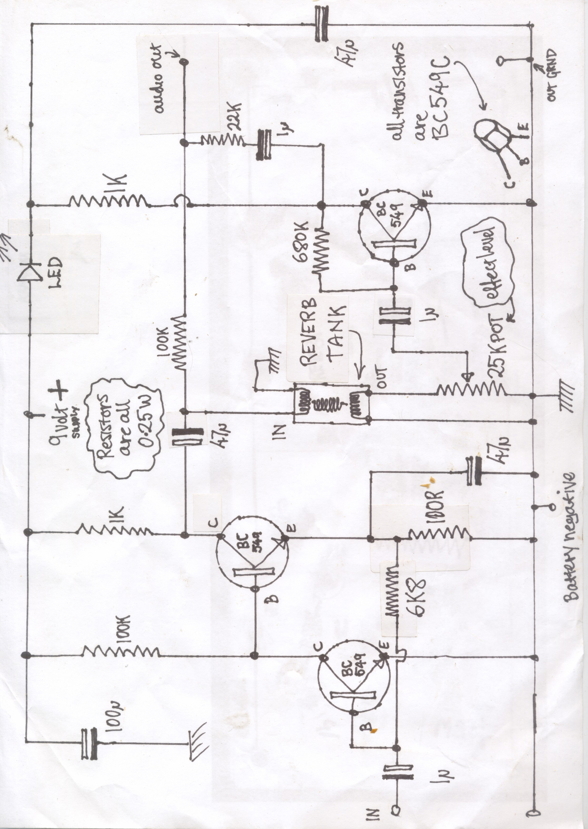
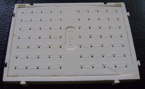
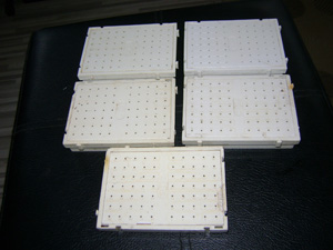
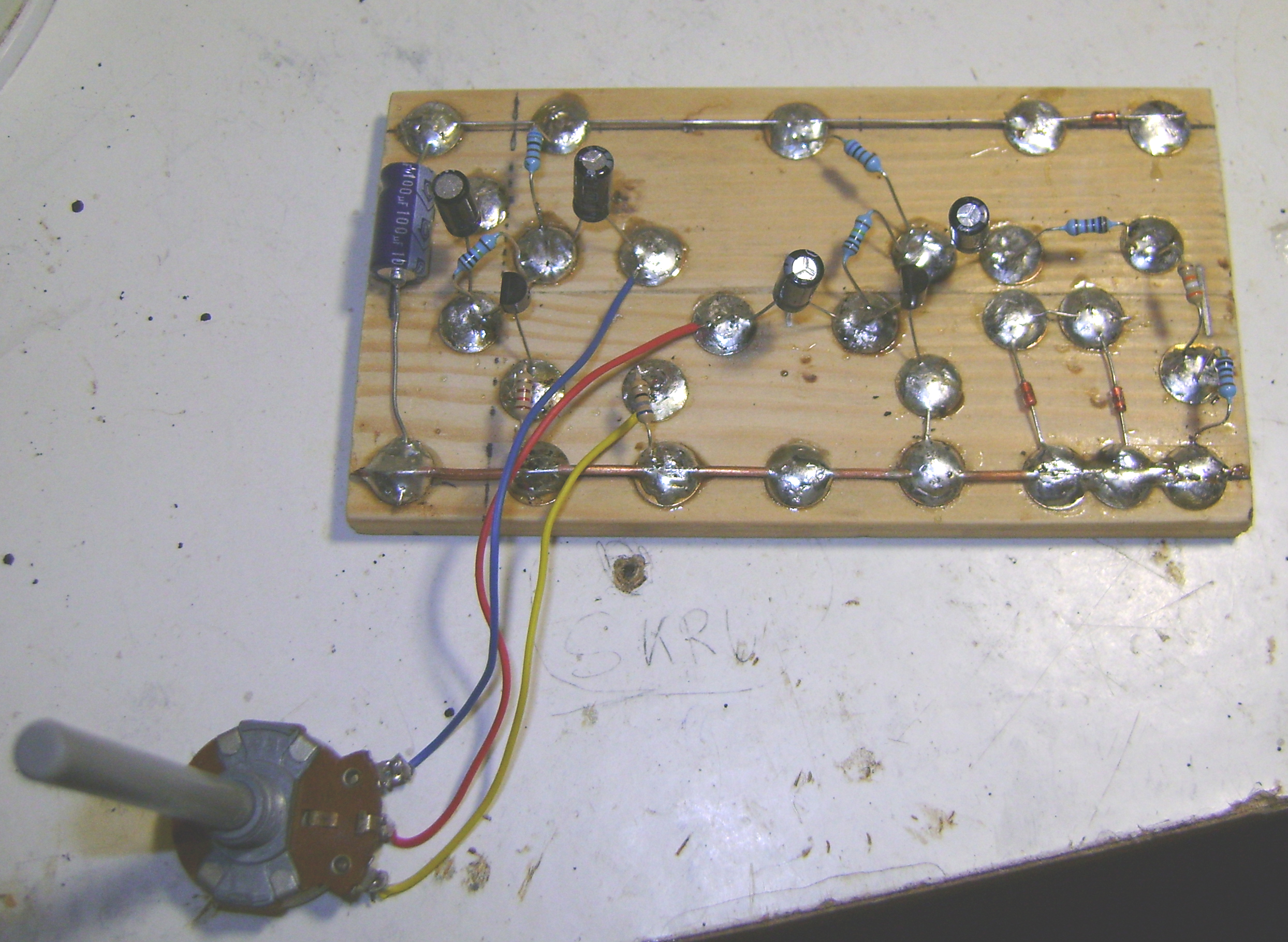
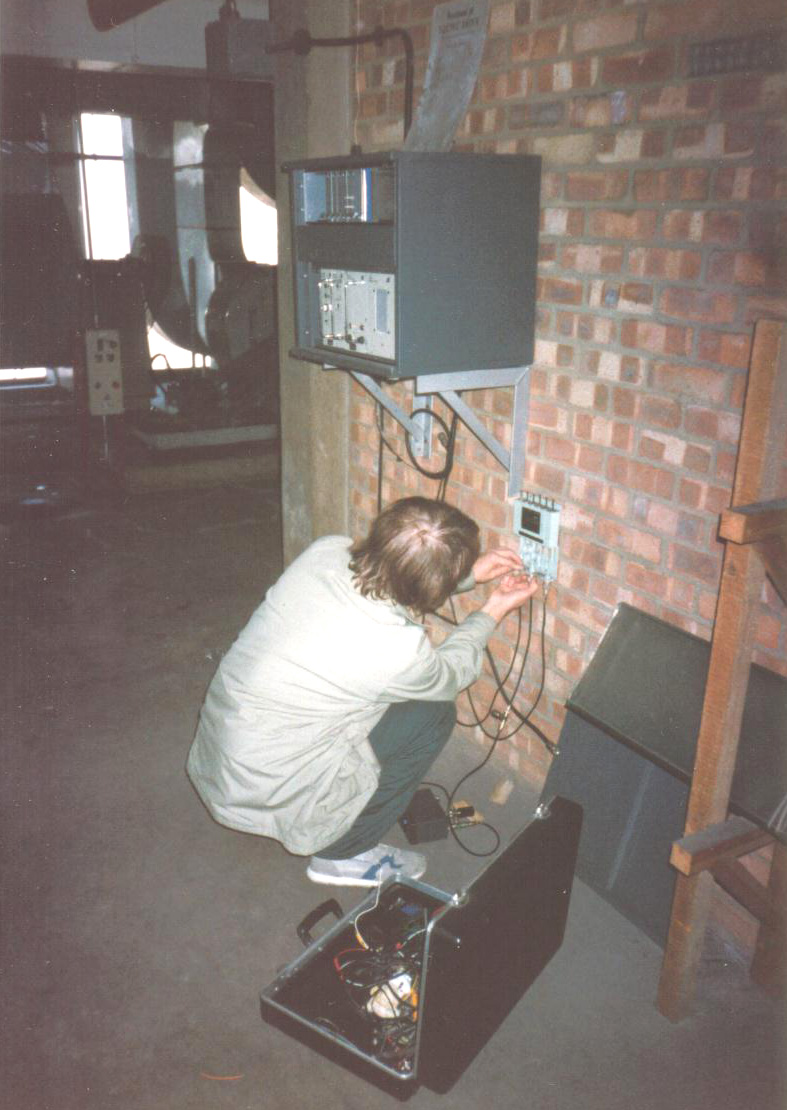
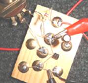
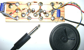
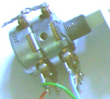
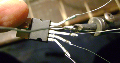
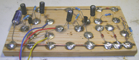
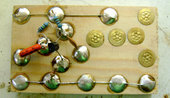
Build
the circuit as in the diagram using drawing pins on a wood base-board and solder
components onto the drawing-pins: simply copy what Ive done in the photo.
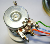
Using only one of the outer tags and the middle one of a 2 megohm potentiometer,
connectbetween base and collector instead of RB using crock-clips or soldering. Connect the PP3 and adjust
the 2 meg pot until you get half of the supply voltage between point X and emitter.
Keeping the shaft still, disconnect and measure the potentiometers resistance:
this will be your value for RB and the resistor selected accordingly. This
circuit should work with transistor types: BC107, BC108, BC109,
BC547, BC548 and BC549. In fact, any bi-polar transistor will work as long as
the correct connections are adhered to: Please consider that some transistors,
such as the amazingly high-gained BC169C have collector connection
in the middle and base where the collector would otherwise be.
|
|
|
|
Pre-Worked RB RC
Table for a BC547 (hfe = 200) using VCC at + 9 volts.
|
|
Collector
Load Resistor: Ohms
|
Base
Bias Resistor: Ohms
|
Collector
Current (Ic)
|
|
180
|
47k
|
25mA
|
|
220
|
82k
|
20mA
|
|
470
|
130k
|
9.5mA
|
|
1k
|
270k
|
4.5mA
|
|
2.2k
|
373k
|
2mA
|
|
4.7k
|
770k
|
1mA
|
|
10k
|
1.8Meg
|
450uA
|
|
|
It doesnt take much imagination to occur that you
can feed an output of one stage into another one and get more volume, as done
below. This
can be done by connecting two or more of these circuits in cascade. From a design point of view it is better to start from the premise
that we require a clean signal so wed then select appropriate resistance
values to pass a higher (25mA) current for the last stage: the first stage is left as above
and
the second would have 180R as RC, 47k as RB. We could substitute the
180R collector resistor with a high impedance loudspeaker. Commonly
available loudspeakers of this type are 65 80 ohms. It's not capable
of marshal 200 watt performance:
the best this simple amplifier can manage is a quiet practice
amp for use in a personal space, primarily, presented as
a means of grasping fundamentals of amplifiers/effect pedals electronic
operation.
|
|
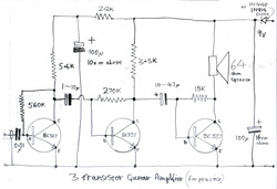
Stains Three Transistor Guitar Amplifier
|
|
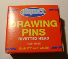
Like
it says on the bocs ! Drawing pins come in varous sizes
but these little cheaper ones are best for these projects. If
you use the more common larger ones, they need to be
spaced out a bit more, which will involve using a
bigger bread-board.
|
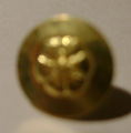
Drawing pin as it looks when
separated from it's mates and taken out of the bocs. They need to be kept in
a tin with a tight fitting lid to prevent escape: Standing on them barefoor
by accident is
excruciating !
|
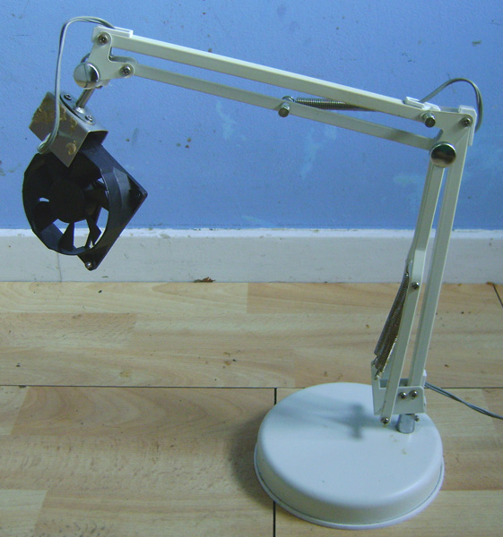
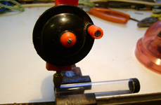
Calling all inventors: please invent this!
Solder fumes contain nasty substances that irritate noses. We need to dissipate
them into the surrounding air away from our face, the fan positioned close to
our workpiece. Solder extraction gear is costly: this simple device, consisting of an old angle
poise lamp frame and a computer fan does the trick.
|
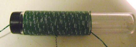
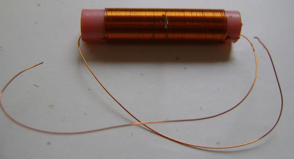
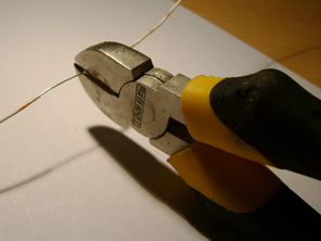
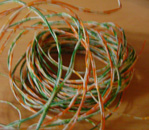
Wire:
so much of this thin solid core stuff is thrown out
by telecomm engineers and sold off cheap in electronics
shops that it's worth collecting up. It's perfect for
these 'pintronics' projects.
|
|
This
simple amp can be used for other purposes: forming the
basis of an intercom or amplifying a crystal radio.
Being limited in output power, it overdrives easily
giving a crunchy sound desired by some guitarsts. The
BC 337-16 is available; 99p for 25 (eBay).
Theyre obsolete, because the hfe, Beta or Gain is low: the examples I
bought from eBay were only 40 - 70. However, the low gain enables simple
construction such as the old-fashioned drawing-pins-on-wood method: unsuitable
for BC 109Cs or similar high gain types as we may get
resistive
coupling causing transistor bias problems. This produces poor sound quality/unwanted noises from the speaker: wood is not a great insulator,
according to Sir Clive Sinclair, getting worse
in damp environments.
|
For improved
screening, also necessary for high-gain transistor types,
we'd need a metal case because wood provides
no screening. Metal working makes hard work of our project
and is costly. Circuit instability
makes noises at the speaker and consumes a power amplifiers limited output
by
emitting inaudiable frequencies. Some circuit designers use
shunting
capacitors in selected places but it may cause other instabilities and reduces
the HF response. Terminating resistors can be used, also adding to circuit complexity:
to be discussed later. Unstable circuits, though, can
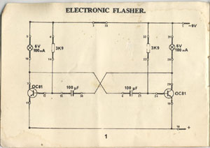
be used for sound effects. During project planning, the thought occurred of
using Germanium transistors. However, a typical type number such as OC81, is
£2.50, being rare.
|
|
!
|
Transistor hfe or gain does more to affect input impedance
of an amplifier than make what it's working in louder. Electric guitars have inbuilt volume/tone
potentiometers, typically 250k and there's also the parallel wired pick-up coil, so combined matching would
probably be less than 100k. For this reason theres no point in
having a 1 Meg input impedance amp for a guitar. If you wanted to connect a
Xtal mike or pizo record player P U, then this order of impedance is appropriate.
A hoofbags
music/sound engineering trick is to feed an output of one of these amps, via
screened lead, to a remote speaker in a box, also containing a microphone. The
microphones output is then sent back via another long screened lead to our
Studio 100. Bassman Sid then gets his over-driven
bass sound, rich in harmonics and sustain, desired
for Electric Cheese Trolley music.
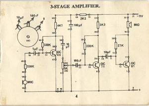
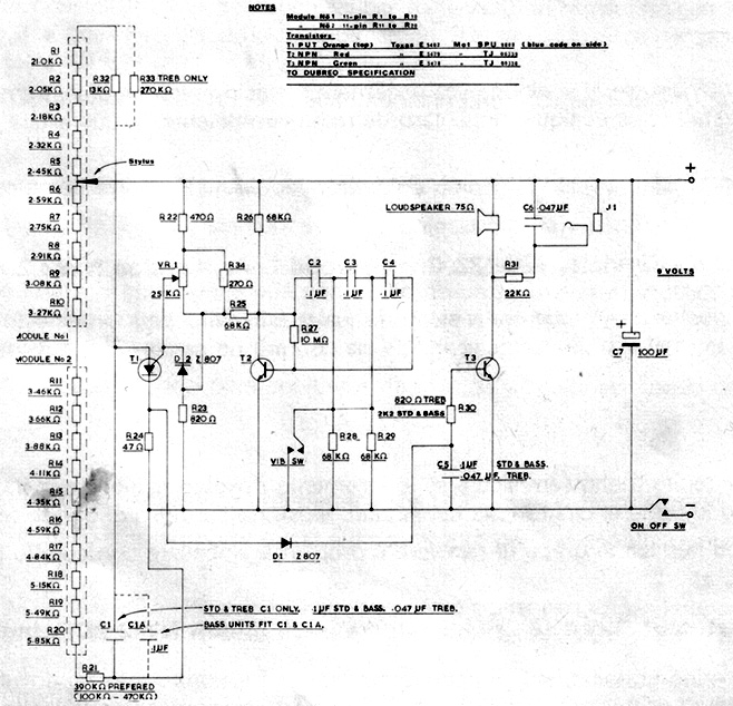
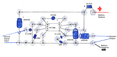
Interstage
Decoupling: On the diagram's left side is a 2.2k resistor
and 100mfd capacitor. These filter out any voltage fluctuations
caused by Tr2 and Tr3s operation that would affect
transistor 1. Missing these components out may lead
to 'motorboating', manifesting as an unpleasant noise
from the speaker. The right hand 100mfd capacitor helps
extend a battery's useful life.
|
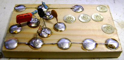
|
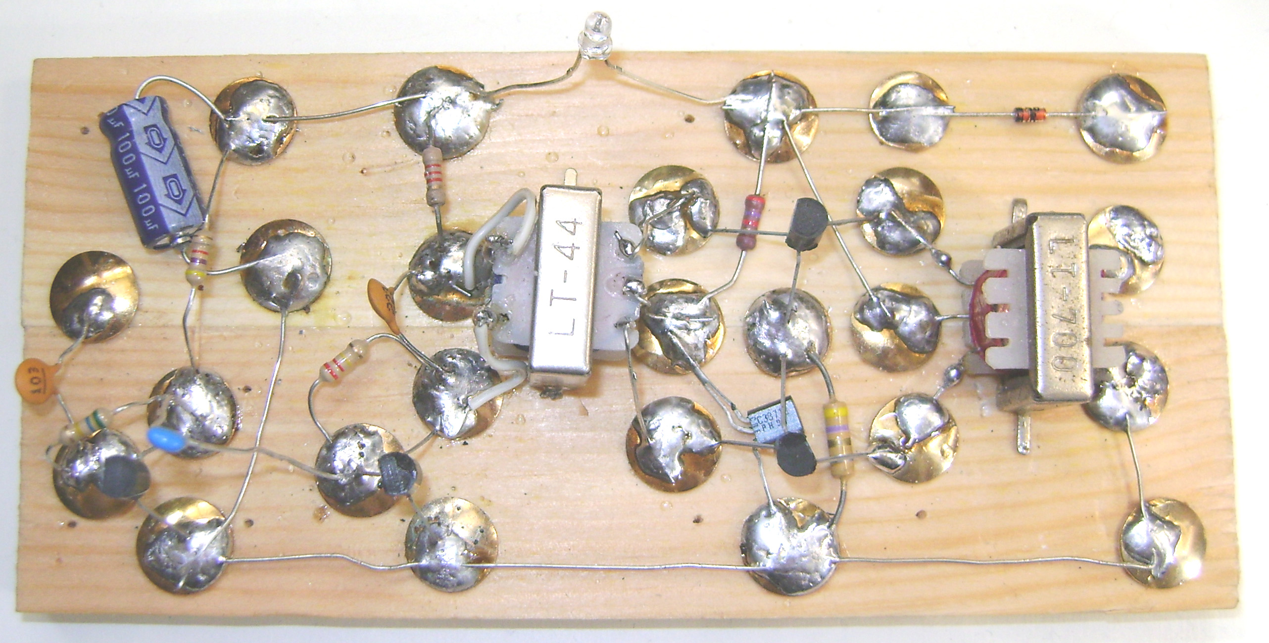
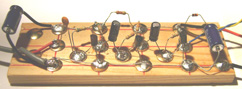
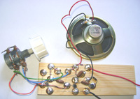
As a continuation of the designing simple transistor
amplifiers section on this hoofbags Website, we have three of the above
circuit (at the start of this section) strapped together on one bit of 5"
long wood. This stuff is
sold as baton for boxes and is 3/8ths thick, 1n half inch wide. In mm, to be Euro friendly: 127 mm long X
44 mm wide and 7 mm thick. If you used thinner stuff the drawing pins
might cause splits, but just about any lump of wood would do. Balsa is unsuitable.
One
amplifier stage feeds into the next (cascade) and provides enough volume for a
transistor guitar amp that is loud enough for practice purposes, and more. It
can form the basis of a fuzz pedal, and a means of connecting to a bigger
amp, in which case this would be the pre-amp, will be investigated and described in an update. This
amp as used here with it's speaker is about as loud as a small transistor radio
and will work from a battery such as an Ever Ready PP3
or PP9.
|
|
|
Wire
We require tinned copper wire and the old style BS3036 used this it's usually suppoied on a card and can probably be bought from electrician shops or even hardware stores. Being tinned isn't essential, a lot of telephone wire comes as plastic coated copper. This works fine. Also eBay: do a search for telephone wire.
|
Here
at hoofbags, and coz we're skint, we like doing stuff on a budget,
and its also why we still use an old but functioning Amstrad Studio 100 'what
Sid rescued from a skip'. If you attempt this ultra-budget design a beginner
will understand fundamentals of audio electronic amplification.
This may lead to a reader eventually being able to design their own circuits
and enable self-repair of amps such as Pignose and effects
pedals.Theres another issue: if you go to
Maplins you'll see 0.1 matrix board for soldering chips and
other parts to, for a self-build. You can use one of the
excellent Antex miniature solder-irons but these are hardly hot enough to melt
this modern lead-free stuff weve all got to buy. When it eventually melts, it's supplied in too-thick a gauge to be used with 0.1
and the chances of causing adjacent track shorts makes the entire endeavour
anything but an enjoyable craft hobby. I've lost my camera USB lead. When I
find it or get a replacement I will present powerful
LM383 and LM386 designs that can be built in this way.
|
|
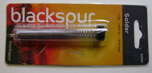
For
these projects I've used a Black Spur 30W at £2.00 from
ESK. Theyve got a fat bit that's hot enough for unleaded solder. If youre new to soldering, a temptation is to try conveying molten solder
on the iron tip to the joint, using 'melted solder as glue, plonking it onto a joint. This is incorrect! You must, in the case of a
drawing-pin, heat one up already in the base-board, to the point that
it will melt the solder upon contact. This is to be done on component leads,
too. Don't worry too much about solder damage to transistors or other
components: its difficult to even deliberately cause component
damage when soldering lead-outs. This caution was propagated because early germanium types were more fragile and a
budget transistor would cost about a days wage.
|
|
|
|
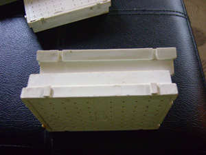
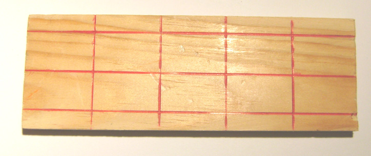
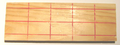
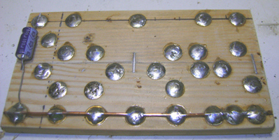
Take a bit
of 1.5" X 3/8ths" softwood baton and saw it
to 5" long. Using a pen, mark it out with
4 vertical divisions, as in the photo with 1" sections.
Draw a centre-line horizontally. After that, draw another
two that are a quarter of an inch from the top and bottom
edges. The line inter-sections are drawing-pin insertion
guides.
|
|
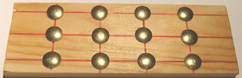
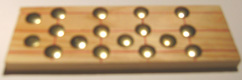
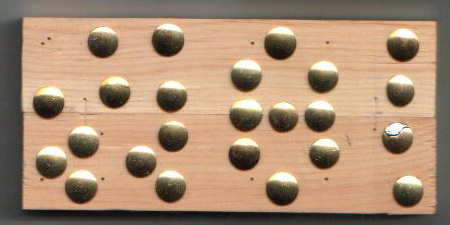
With drawing
pins inserted into the baton: our baseboard,
it should look like the right-hand photo. We need to add more pins and should look a bit like
the rather out of focus photo below. (appologies!)
|
|
|
|
Wood can
withstand solder-iron tempratures for some
time; resulting heat damage is minimal.
|
|
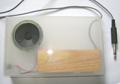
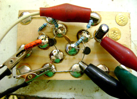
It's entirely
possible to build the amp from careful examination of the large-view
photo avaialble from clicking on the hyperlink picture:
right.
|
|
|
Component List:
A high impedance
minature loudspeaker: of any value between 65 - 100
ohms.  lyn3009
eBay Item number: 360026730614 lyn3009
eBay Item number: 360026730614
Three of BC
337-16 transistors. auntyant2
eBay. Any BC 337 will
work but not sound as good. Alternatively: adjust base-bias
resistor values.
18 of the smaller
size drawing-pins, aka: thumbtacks.
Two of 100 micro-farad
capacitors.
A 47 micro-farad
capacitor
A 1 micro-farad
capacitor (both can be substituted with 10 mfd
but almost any value would work)
1N 914 or 1N 4148
diode (almost any similar type would work)
Resistors: 15k,
3.3k, 270k, 2.2k, 5.6k, 560k.
|
Other Bits: bit of wood, ball
point pen, ruler, 1metre of screened cable with a guitar
type jack plug on the end, thin tinned copper wire of
about 26 swg or similar, about 1 metre of single flex
to wire up the speaker and battery, 9 a volt battery
or mains adaptor set to the appropriate voltage.
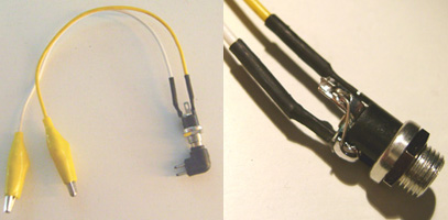
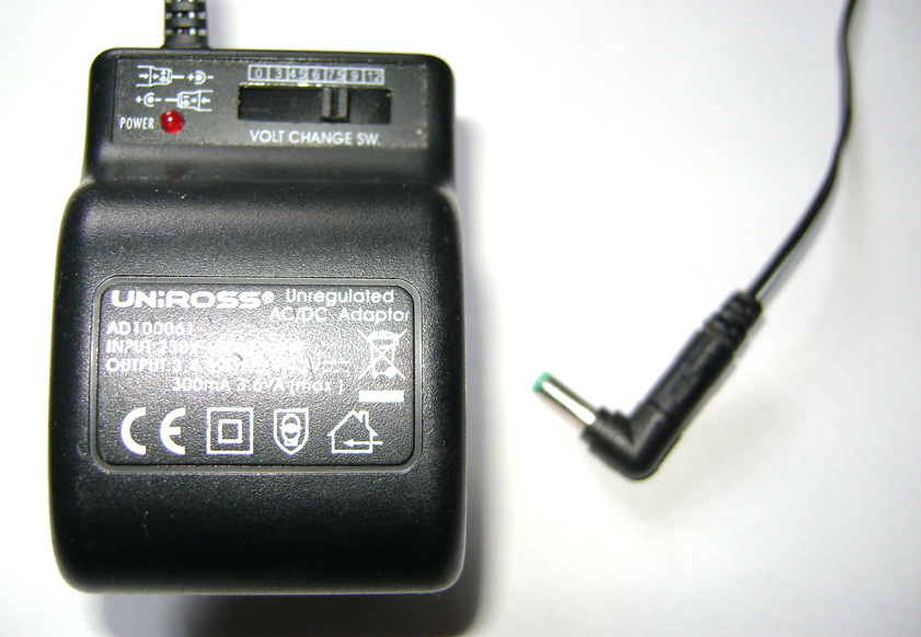
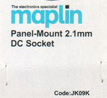
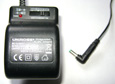
An
essential item: a means of powering up and testing projects in development. Maplin part No: JK09K with crockadile
clips attatched. It enables a £3.99 Uniross AD100061
multi-voltage power plug to be used. PSU polarity is
determined by the co-axial/two pin pluggie bit's direction.
If project don't work upon competion, reverse crock-clips.
|
|
Power supply
socket connection details (+ pin)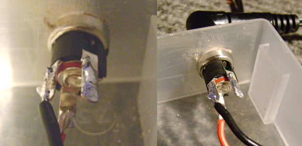
|
This amp specifies 9 volts. Budget power
adaptors are poorly regulated, giving higher voltages than on the selected rating
switch. In which case, it's kinder
to the transistors if 6 or 7.5
volt setting is chosen. The amp might be
louder at higher voltages but be prepared
to replace T 3 regularly. Under
such circumstance, T 3 gets hot enough to
cause injurious burns, if touched.
Always included, is a 1N 914 or similar
rectifier diode, in the circuit's top-right
corner power line, preventing reverse
supply damage. To establish correct PSU
unit's polarity, in event of project
initial non-working, simply reverse the
2-pin/co-axial plug into the lead-end.
|
|
A
Dead Town Cat Playing Guitar Through a Homemade
Stainamp
If you
have any trouble viewing this, please right-click
and download.
|
|

|
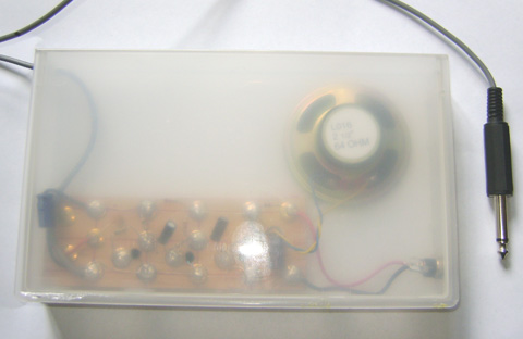
If you're
any good at carpentry a wooden case would
be ideal. For a quickly finished project
however, an old VHS storage shell can
be used and you even get see through type
iMac styling! I
used hole saw attatched to drill for
the speaker hole but if you ain't got one,
make hole with soldeing iron. If
so, be sure to clean the tip off immediately
afterwards with damp cloth and do the melting
in a well ventilated area: melted plastic
fumes is nasty! It may also be possible
to make the hole with a craft knife or copying
saw. Another smaller hole can be drilled
to accept the co-axial power connector.
To stick the parts in, superglue won't work:
you must use Evo Stick.
Unfortunately, this is exactly the type
of glue that some folk get high on:
If your local store won't sell it to you,
tell them to shove it and go elsewhere.
I got problems with this scenario: I often
needed to buy the stuff and, being an ancient
hippy, I got accused. In truth, just
using the stuff is enough to give me a headache
and deliberately sniff it, I should coco!
|
|
|
Get your anoraks on,
we've some points to consider: Although this is a
simple circuit, there's a surprising amount of stuff going on. For example,
if using ohm's law, we
were to work out a speaker impedance at 25 - 30 mA it would resolve at around
the 160 ohm range instead of 65. However, using this order of collector load
would limit output power and cause the circuit to function incorrectly. When
the circuit is making a sound, there is an AC (alternating current) content
superimposed upon the DC, (direct current) flowing through our BC 337. This AC
frequency, determined by which note your guitar is producing, will cause the
collector current to fluctuate. Viewed on a suitably configured oscilloscope, it'll
be seen that
the current will increase to perhaps 41 mA on the peaks and decrease down to,
say, 19 mA on
the troughs. When reproducing a guitar signal, an overdrive is often accidentally
or deliberately opted for so,
these fluctuations may be much more. It is therefore appropriate that a
speaker load impedance is specified that will more accurately represent a correct
load during these transitory peaks. There are other issues occurring: those of
thermal runaway. It is a fact that the hotter a transistor gets, the more
current flows between its collector and emitter. Unless kept in check, the resulting increase of
current causes a further increase in temperature. This cycle will continue,
assuming the presence of an uninterruppted supply current of course, until the
transistor reaches saturation or the bias conditions render it un-useable. Here,
the problem is eliminated because we
take our base bias at the junction of the
|
transistors collector, and its
load. Now, as the transistor warms up, conductivity increases, and has the effect of a reduced voltage at the collector junction. This
causes a matched reduction in the base bias current.
It behaves in the same fashion as a
speed governor on a steam engine. This
arrangement is commonly known as collector-base biasing, because the base
bias resistor is strapped between the collector and base. In older electronic
hobby books, one may encounter simple bias arrangements where the
base resistor goes directly to the supply rail. Probably, these circuits
were designed at a time before the complicated scientific principles behind thermal
runaway were fully understood. Ive noticed an improvement in eBay available 65
ohm 3 speakers recently. No bad thing at all! It is often considered that, in
place of a suitably high impedance speaker, an audio coupling transformer and 8
ohm speaker may be substituted: This may work, or perhaps problems could be
encountered. A suitable transformer, especially if its large, may not have a
sufficiently high primary winding resistance to the DC, which will disable the installed thermal
stability measures. If a transformer is opted for, a
good choice would be a commonly available Eagle Electronics LT 700, which has
a primary resistance of about 72 ohms. However,
comparable output results might not be achieved. There is a commonly used transistor
biassing arrangement where the collector load matters
a lot less. It's called the voltage divider type and
uses about twice as many resistors and an extra capacitor.
It will be explored in an update. Watch this space!
:o)
|
|
|
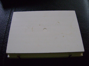
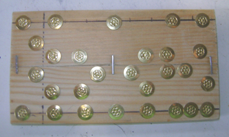
Wood
is just over 2.5" x 5.5" x 3/8" thick
(picture is near actual size) 24 drawing pins are inserted.
Make sure none of the pin heads are touching.
This spacing allowes for easy connection
of the specified components' leads when
new.
|
|
|
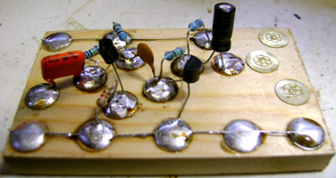
|
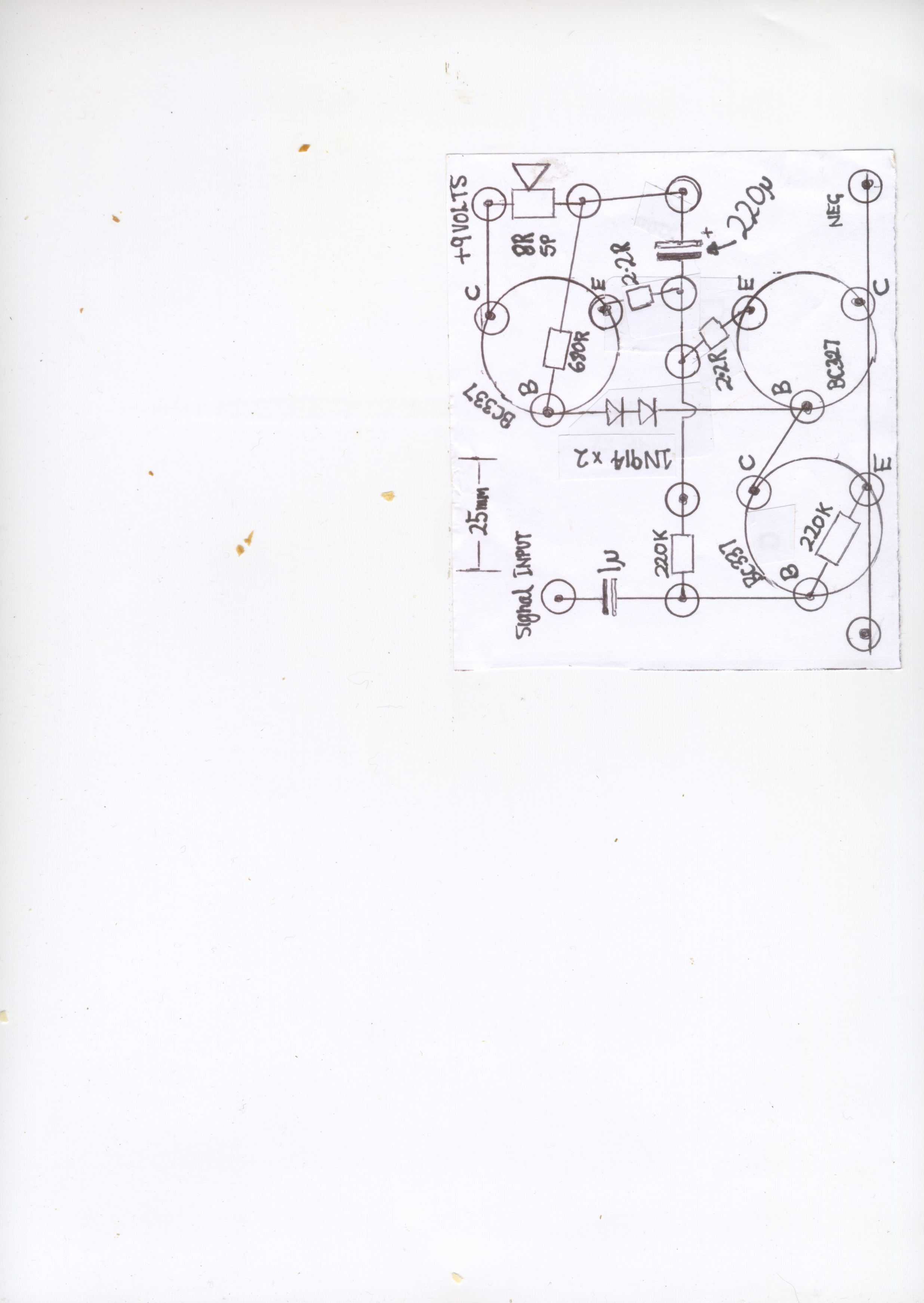
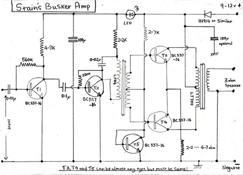
The 3 transistor
design above is only capable of between 10 - 30mW. That's
enough volume for practice purposes but if the guitarist
needs an amp for busking, it would need
to be louder. Another problem with the 3 transistor
design is that it uses up the battery at the same rate
irrespective of the volume setting: being of 'class
A' biasing configuration. The 5 transistor design suggested
here is volume verses battery life inversely proportional
because of it's 'class B' biasing. It's capable
of 300mW RMS with a 9 volt supply and about 600mW
with 12v. It may be possible to get more at higher
voltage: up to 14 although higher than this may cause component
damage. I'm using 2 mini transformers: LT44 and LT700.
These are stocked by Maplin's occasionally, and other
sources such as through an eBay search. T1 and T2 should
be BC337-16. T3, T4 and T5 can be almost any NPN TO92
plastic general purpose audio, however, for best performance
they should be 3 of the same type number and specification.
Needless, BC337-16 is ideal. The LED, blue in this instance,
serves three purposes in this circuit: it drops 2 volts
for intersatge decoupling, lets the user know that it's
on and it looks nice. Naturally, in the finsihed project,
LED may be front panel mounted and interconnected
via wire.
|

This
amplifier's design has been around for long enough: it can be found
in every transistor radio up until the late 70s
and the legendary Pignose 5 watt is reasonably
similar.
|
|
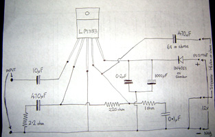
Current flow: under
2mA, through LT44's primary is limited via the
2.2k resistor. Without this (via direct wire connection)
current woud be about 6mA and the poor little LT44 doesn't
like it very much. It will over-heat and go open circuit.
The LT700 data sheet recommends a 3.2 ohm speaker, 3
ideal. 3 ohm speakers are a bit rare so 4 ohm will do.
An 8 ohm is useable but there will be a reduction in
much needed volume. a good size for this would be about
4 - 5". Any size would do. Note also that transistor
T4 has its flat side facing the opposite way from the
others: For T4 the flat side must face to the
right. Also important is the correct LED connection.
In this example the flat denotes the cathode and negative,
which faces left.
If the light don't come on the amp won't work: try re-soldeing
the LED the other way 'round.
|
There're transistor
interstage transformers in existence smaller than
LT44s / LT700s but all are still referred
to as minature. One issue about these components' size
is that, in order to get enough turn's winding within transformer
coils, the wire must be very thin: the wire
of an LT44's primary, at about 650 ohms, is
as thin as hair! Thinner wire means higher resistance
and that reduces the maximum current that can flow
through it. Consequently, in combination with
the limited mass of the transformer's iron core, the
output power is limited. Larger transformers can be
used in this circuit without modification of any other
components, with exception of the 2.2K which can be
lowered for bigger transformers if necessary and T3,
T4 may need heatsinking. These
transformers must be of the type specified for transistor
driver and output and can occasionally be salvaged form
very old transistor radios. 2 or more watts RMS is easily
feasable.
|
|
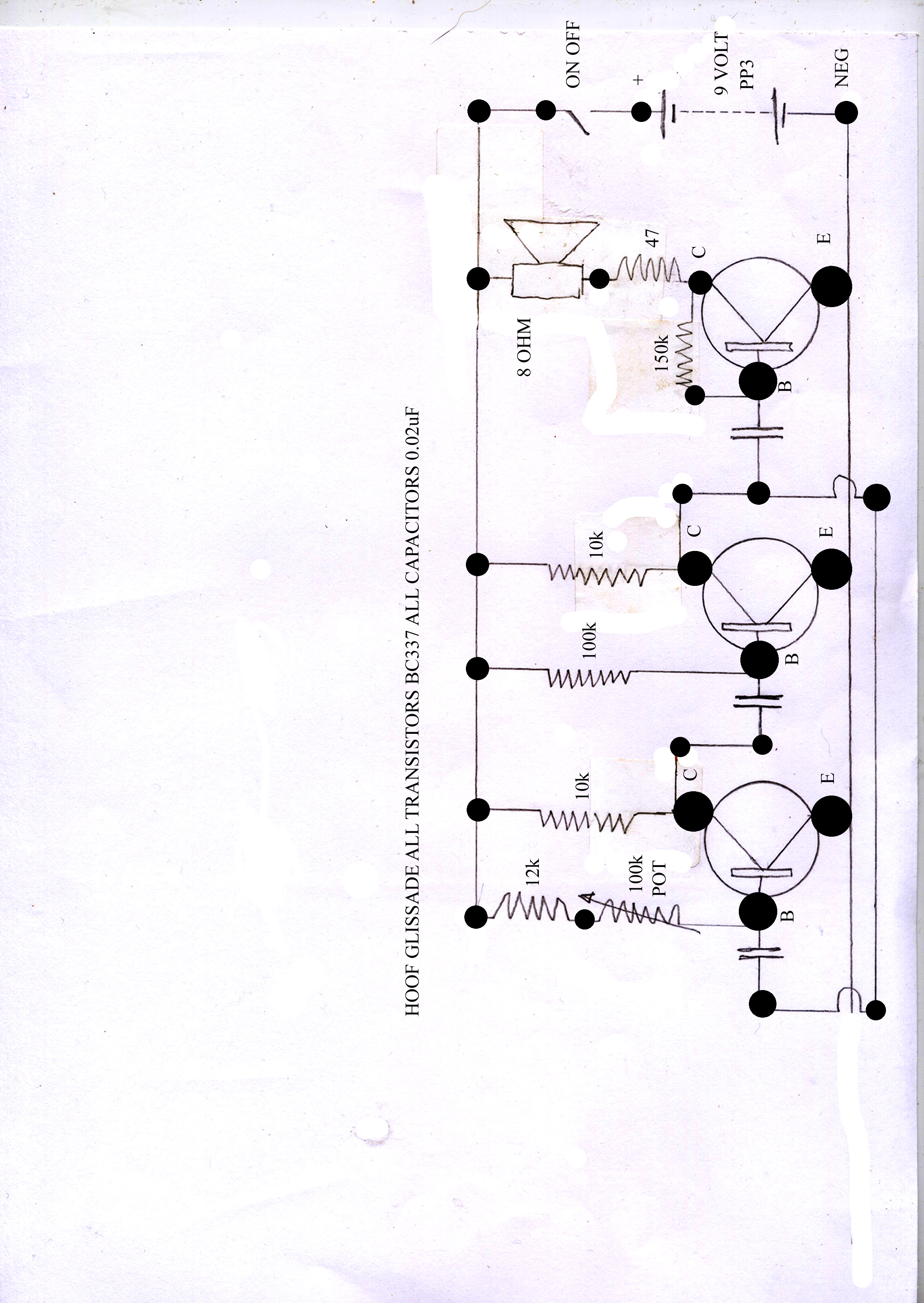
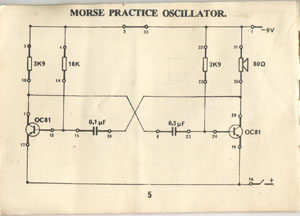
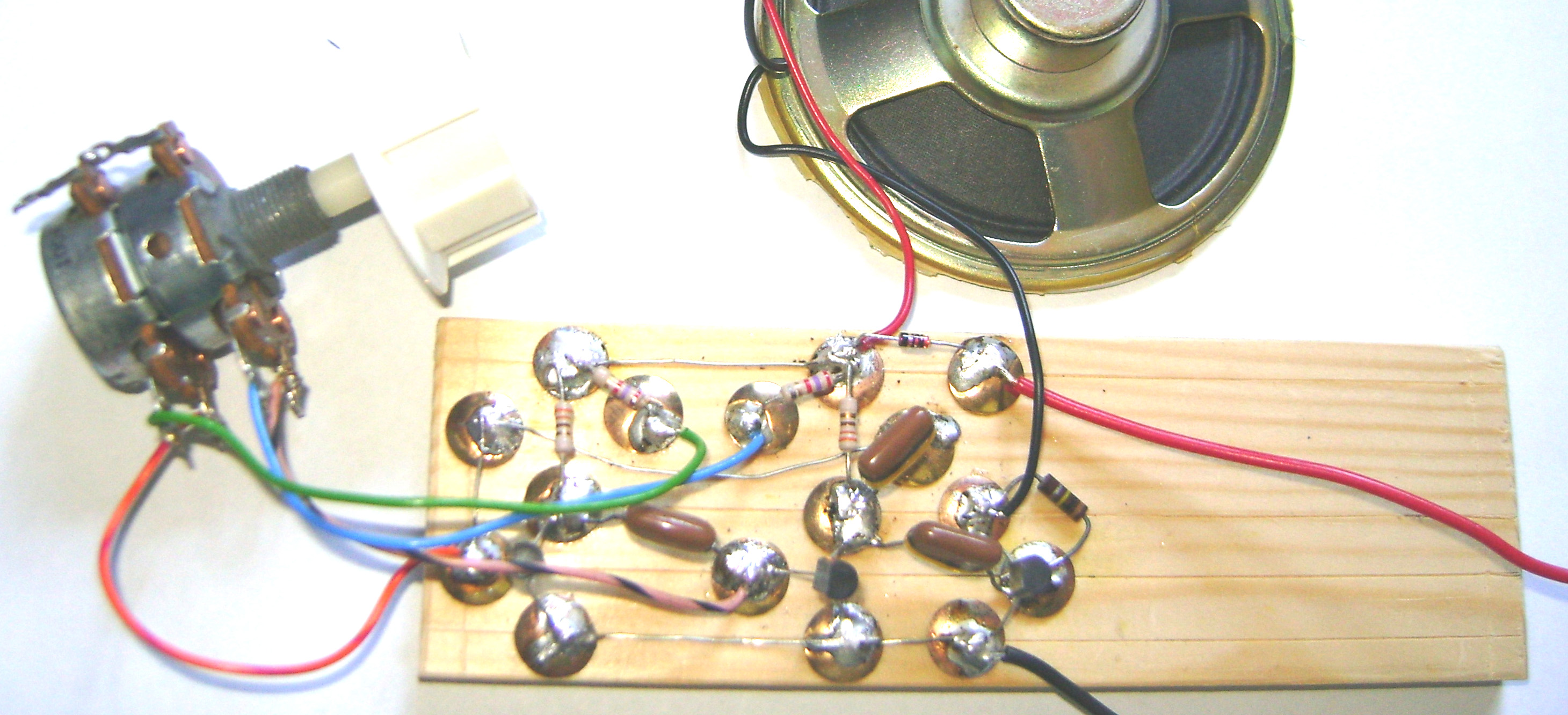
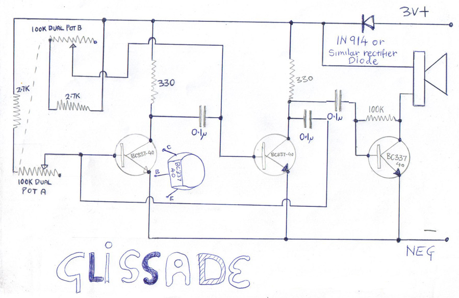
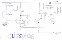
Stains glissades:
easy to build simple audio VFOs
|
|
'Glissade'
means 'slide' in another language and they
seem to be making a comeback in some Drum
'n Bass music. Additionally, Elis uses one
in the Electric Cheese Trolley music tracks: see INDEX
above. A similar type of tone generator
is the Theramin. However, Theramins are
rather complex bits of kit working
at radio frequencies. I've a design from
a 1960's book 'Having Fun With Transistors
by Len Buckwalter. It's a very simple circuit
consisting of two transistors but some other components are no longer available.
I'm gonna work on it ! Whereas Theramins need
no physical contact, with a glissade the pitch is varied
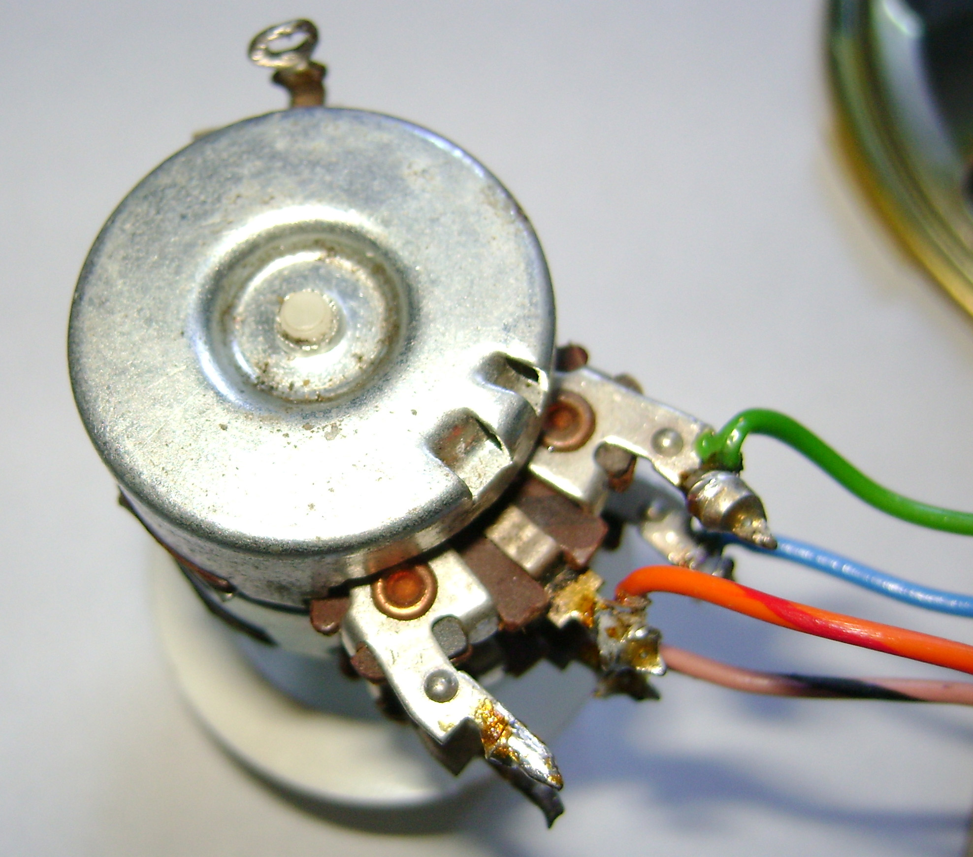
by rotating a potentiometer.
There will also be a means of volume adjustment,
later. Glissades are Variable
|
|
This
means we can upset the base bias setting to an
extent that wouldn't allow a linear audio
signal to pass through. The bias is controlled
by the dual potentiometer. (Below)
The output frequency is determined by the
time constant of whatever the 100k potentiometer
is set to, multiplied by the 0.1 micro-farad capacitors:
The resistance value is multiplied by the
capacitor value to derive T. Then
divide 1 by the result to get ' f ' = frequency.
Many glissade designs have only a single
potentiometer, and may be presented here
later.
However, I've found that a dual pot seems to give a
much needed wider frequency range.
|
|
|
Frequency
Oscillators working in the audio range.
Examining the circuit diagram, it can be
seen that it's based on another amplifier
presented in this section, and, with the
addition of an extra drawin-pin or two,
the same arrangement can be used as in the
three-transistor amp above. The amplifier
output is fed back into the input and we
get positive feedback. It's a similar action to when
someone sticks a microphone too near its
amp; called
'howl-round'. Another description
of this circuit is 'astable multivibrator',
where the amplifier gain is said to
be infinite. Because we aren't dealing with a linear
audio signal, as in a conventional amplifier
circuit, distortion isn't an issue.
|
|
|
|
|
|
|
|
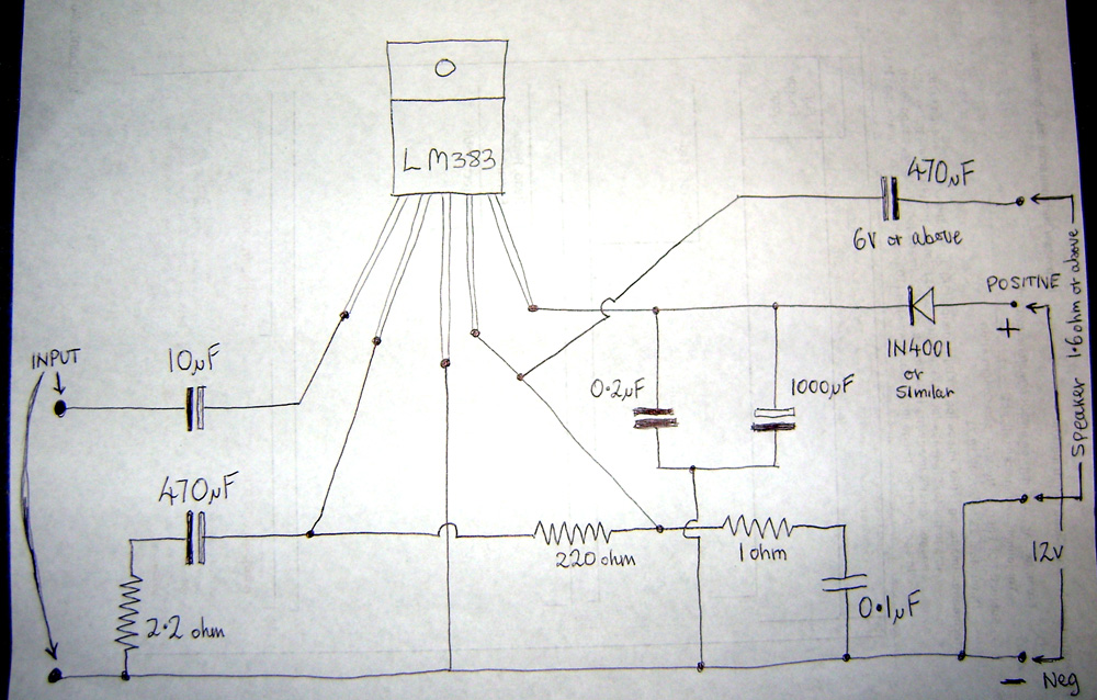
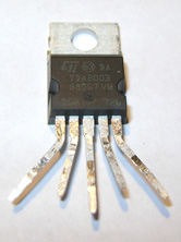
The LM 383, or its equivalent
the TDA2003, is a common IC
found in amps sold as 'guitar packages' from catalogues: you get the
guitar, amp & lead in one box: Typically the Park-Marshall 10 watt
ones. These amps dont seem to last very long, though: Ive often been asked to
repair these and the usual fault is the output amp chip is burnt out. Aother
problem is the potentiometers fitted into these are rubbish: they get noisy in
no time at all and replacement isnt an option, being non-standard. If you
manage to get them, the printed circuit is hardly robust enough to withstand
the de-soldering & re-soldering of any faulty parts. Pretty much, these are throw
away post warranty units....
|
|
|
...The failings aren't down to the LM383 chip,
though: Ive built loads of circuits with these and they dont go wrong. It
only happens if the supply voltage is maxed out to get a higher output. I always prefer to keep supply voltage
lower than 15, ideal for a 9 12 volt battery busker-amp, and use a low-impedance
speaker. This may be achieved by connecting two 4 ohm speakers in parallel
to get 2 ohms. However, the LM383 will drive loads down to 1.6 ohms.
|
|
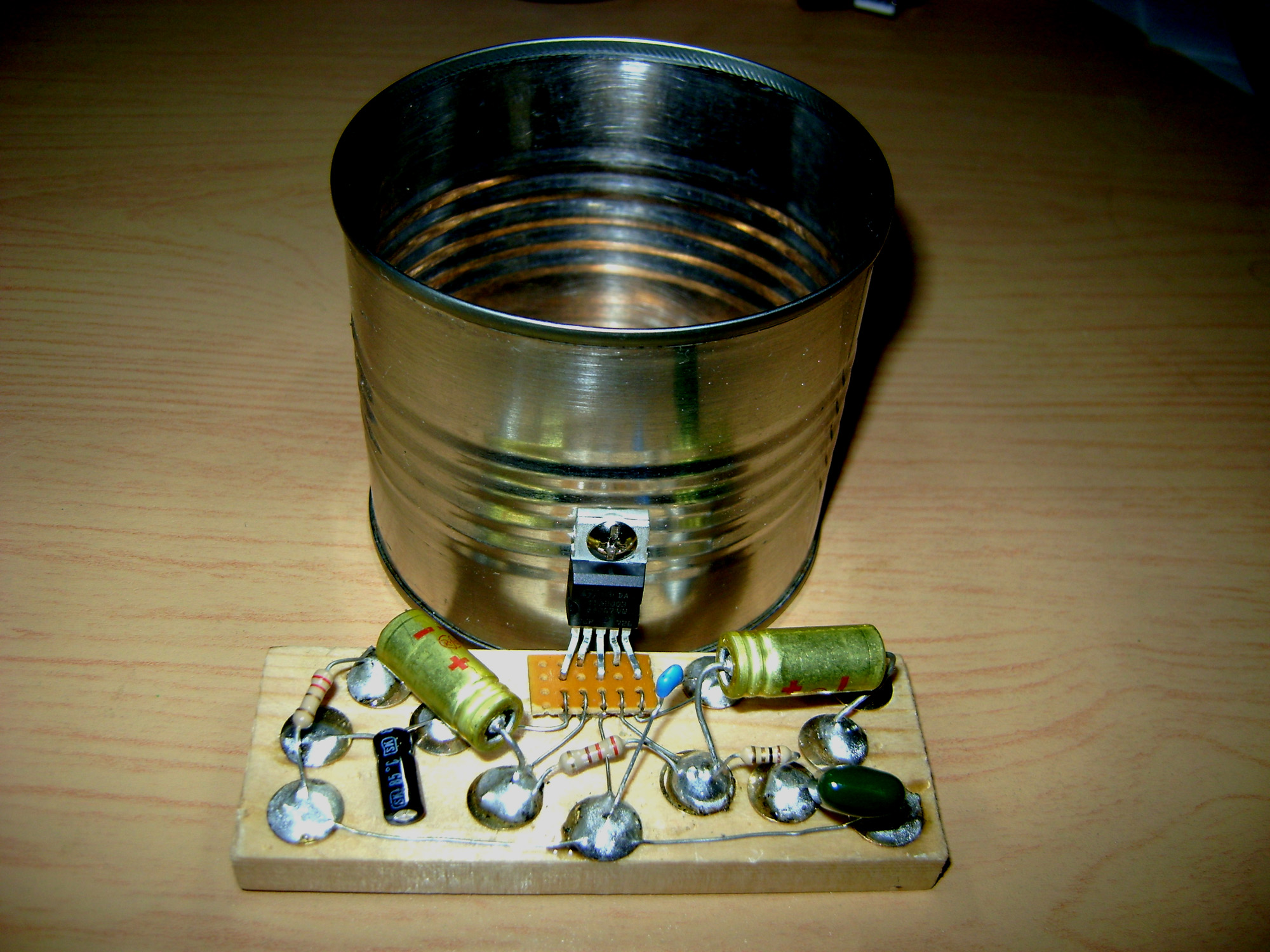
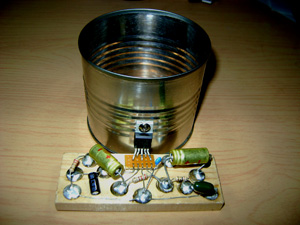
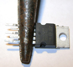
In the photo a bit of veroboard interfacing is
used as a means of extending the LM383 lead-outs;
a bit pointless because one might as well
just build the entire thing with Vero.
I did a batch of these in the event of a
quick amp being needed, that could be chucked
together in a short time. Here, I'll describe
an LM383 amp that can be constructed using
the drawing-pin on wood method, without
Vero. Unfortunately, they don't make these
chips with long lead-outs so if a 'pintronics'
version is going to be attempted we need
to extend the lead-out connections..
|
|
|
In my photo: above right, an M.T.
baked-bean, or any other consumable supplied tin, is used as a heat-sink,
although hardy adequate. Improvements here can be made by an interfacing washer
between chip tab and tin, and using heat-sink silicon grease. Painting the tin
matt black and packing it with aluminum cooking foil will help greatly. Tins have sharp edges: I always run a knife
on inside rim and rub down using abrasive
paper to prevent painful cuts.
|
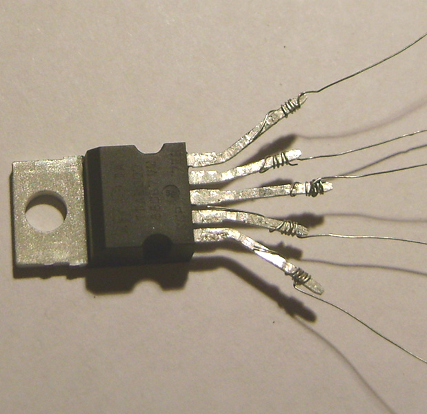
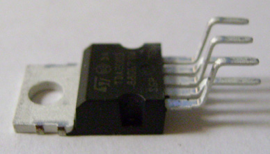 LM383
as it comes out of the packet and ready
to be inserted into a printed circuit board,
if you have one. LM383
as it comes out of the packet and ready
to be inserted into a printed circuit board,
if you have one.
|
|
|
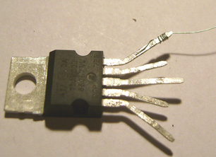
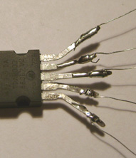
The
chip will come to no harm provided some
precautions are taken during adaptation.
All the legs can be flattened out on the
same plane and then need to be spaced apart
so that they fan out. As with every electronic
component, the leadouts must never be bent
against the epoxy body but at least
one eigth away along it. The LM383
lends itself conveniently here because the
legs become narrower a short way down
their length so providing a definable bending
point. Bending component leads flush with
the body is chancy: there will be times
when we may get away with it. Only an infinitessimally
small crack need appear before the
device won't work. mercifully the chips
are cheap but some effort will be dispensed
in the building of a project only to dissapoint.
|
|
|
|
Thinner
stuff is best for chips because it's fits
more easily between the legs/lead-outs.
It may be a bit fiddly but by no means impossible.
Ideal, is the stuff taken from a length
of flex: It's probably about 30swg. We need
to line it up with the leg that's being
extended, held with a thumbnail and then
wrapped around the leg. It should look a
bit like the one I did in the next photo.
Next, we repeat with the remaining four
legs: Photo on right.
|

|
|
|
I
originally tried using the type of solid
core wire that telephone engineers often
throw away. It's great stuff for making
interconnects within a pintronics board
although not great for an LM383 being too
thick. Next comes the soldering.
To do this it might be easier to mount your
iron in a vice and position the leg to
be soldered onto the tip end applying solder
to the joint.
|
|
|
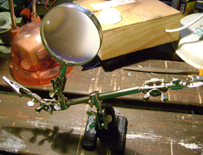
You may also have access
to a Helping Hands craft tool.
|
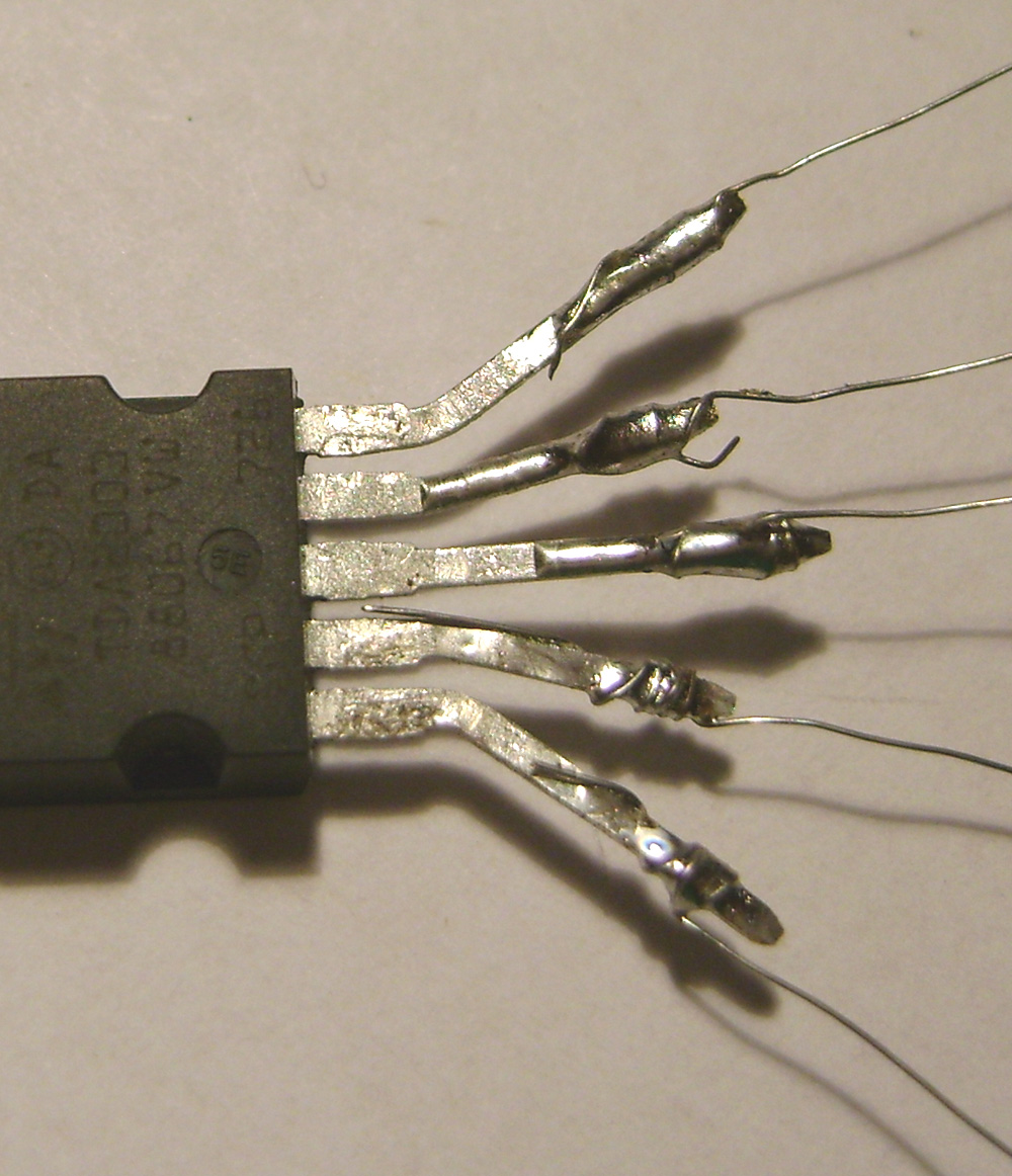
Wisker!!!! Wisker issues: Although the above photos look similar,
one has a 'wisker' on leg No: 2. This is
an easily overlooked unwanted thin wire
that could result in short-circuit,
ultimately resulting in chip destruction
and project failure. In the next picture...
|
No
Wisker! :o)
..it has been removed!
This is typical of a mistake that deters
many beginner electronics hobbyists, but
learned through experience: Closely examin
the components employing a manifying glass
if necessary! It
should also be mentioned that the thin extending
wires can easily break off at this stage
so handling care in essential to prevent
constructional setbacks.
|
|
An
LM 386 amplifier. When the original
386 audio amp chip was introduced, it's
output was limited to 250mW. This is adequate
for such applications as an audio stage
for a walkie talkie for example but not
ideal for guitar purposes. The manufacturers
re-vamped the circuit, increasing it's
output to 940 mW (1W). All the connections
were the same so, the LM 386 N-1 became
the direct replacement for the earlier chip.
The more powerful LM 383
|
|
(above) is
a perfect choice for general audio purposes
but I've found it doesn't perform well in
an overload scenario. This may be because
of the LM383's overload protection which
seems to shut it down when reaching it's
peaks: It really doesn't sound at all nice!
The smaller 8-pin DIL 386 addresses this
issue and it actually sounds really great
with an overloading guitar shuved up it's
chuff. This device sounds so great that
if you wanted to build a fuzz-box with only
a 3 volt supply; most guitarists would be
impressed. Almost all battery powered guitar
amplifiers I've encountered recently, including
the reputable Pignose amplified guitar,
has
|
|
|
one.
My circuit in the above pane is a drawing
pin-on-wood version. You may not wish to
bother with this because the LM 386 N-1
has a number of small PCB's available for
it, it's usually available as a kit
containing all the necessary components
and all you have to do is get soldering.
It is worth building this project if, for
example, you're an electronics student who's
been asked to build a small amp, although
you're not allowed to buy a kit for this
purpose. This drawing pin version is also
useful as a break-out-box for taking measurements
such as voltage levels and similar.
One
|
educational
experiment would be to temporarily
disconnect the 47 mfd capacitor between
pins 8 and 1. It will demonstrate a considerable
reduction in gain. Another would be to see
what difference the 0.1 & 10R HF filter
components removal would make: If you were
to hear the same noises on an amplifier
brought to you for repair, you'd immediately
know what the problem is likely to be. An
amp project containing a battery, potentiometer
and speaker would certainly have sufficient
space available to accommodate this stretched-out
LM 386 N-1 circuit.
|
|
One cannot
fault the printed circuit as a general concept:
every electronic device sold has one. However,
if you wish to put together a 'one of' bit of gear
in a short time,
to use a printed circuit board is always
an involved process : you need to draw at least
3 layers of etch-resist pattern using a
suitable felt tip pen. It then
needs to be placed in a ferric chloride
solution and, as I've found, it sometimes
goes wrong. For production runs of more
than one of the same device, where the printed
circuit is essential,
|
a light-box
will also be needed. Radio circuits working
at frequencies of above about 30 MHz will
need a printed circuit because of the criticality
of component position. If you look
inside most guitar amplifiers there's unused
space. It is there for acoustic purposes.
Hoever, some of it can be used to spread
the components out
|
a bit,
enabling ease of both construction and
repair. An additional time consuming issue
with repairs on printed circuits is that
conductors/components are on both sides
and you have to keep flipping the thing
over. I've found that using a strong
light shining through the board and
a continuity tester helps in this process and
is also useful in the endeavour of
reverse engineering. In case the reader
is unfamiliar with this concept, it's where
you draw a circuit diagram using a
bit of manufactured equipment as a guide:
this can be useful in figuring out how a
manufacturer gets 'round arkward design
issues.
|
|
|
|
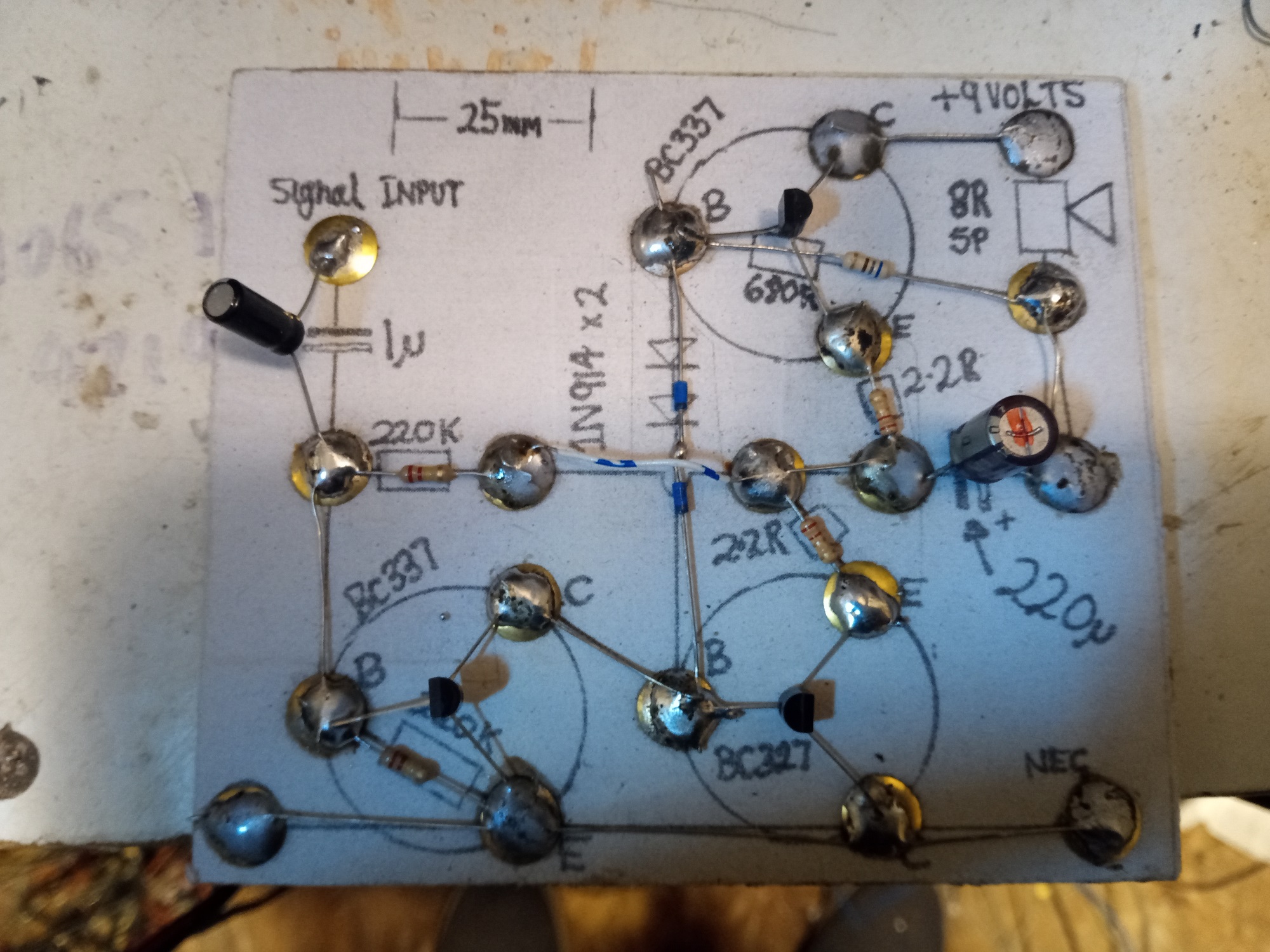
Fuzz
Circuit.
Fuzz is a guitar effect that
has been stated as "the most dramatic guitar effect possible".
Originally, guitar amps were pushed into overload to get a similar effect but
many were damaged by doing this: in particular, the amp's speaker would suffer
and output transformers in valve gear would internally short, destroying the
equipment. Some clever engineer designed a add-on pedal that would safely
create a similar effect and protect the amp. The fuzz effect is derived from
clipping the peaks off a guitar signal. Because the signal clipping produces a
limiting effect, you get sustain. Additionally, there are harmonics produced
that were not in the original guitar signal output. The signal distortion
sounds great for single note runs and major chords but doesnt really work for
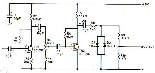
most 7th chords or minors. Here is a fuzz circuit that was found in
an old book called Electronic Projects in Music by AJ Flind. When I originally
built this circuit in the 80s I thought it sounded really good. Ive built it
on occasions since, and for some reason, I was disappointed with the results.
This may be because the original metal canned BC109Cs are difficult to obtain.
The modern replacement: BC549c appears to have a higher gain and, in this
circuit at least, doesnt seem to sound as good. Upon high potentiometer settings
for max effect, the circuit temporarily shuts down and ceases to output. My (humble)
theory is that, the excessive drive from transistor TR1 gradually charges up
the inter-stage coupling capacitor C3 and during this charging, DC flows
through it, upsetting the bias for TR2, pushing it into saturation: turning it
off. The problem is solved by substituting C3, R4, R5 and C4 with an
inter-stage coupling capacitor of 5600pf. It is of a critical value. In this
instance, it would connect directly to TR1 collector and TR2 base. It certainly
performs better than the original circuit although is not strictly speaking a
fuzz effect, more of a clipping sustain. The lowered capacitor value has a differentiating
action and it results in a much reduced bass content of the guitar sound.
|
|
I use a Hohner G3T headless.
(LOVE IT! Only wish I could play it
properly.) The Select EMG humbucker pick up
has a higher output than any cheaper guitars I owned previously and this will
also make a difference to the way this circuit functions. In my opinion, its a
perfect example of refinements in design. Any amplifier, including the one in
this circuit, will distort at high input settings but it is the quality and
nature of this distortion that distinguishes a great fuzz box from a poor one.
The two transistors are intended not to distort a great deal by themselves:
they are just meant to increase the output voltage of the guitar. Although they
do get overdriven and pushed into distortion, the main fuzzing content is
supposed to generate from the 1N914 diodes, where they induce their much
desired clipping action. In practice, practically any general purpose silicon rectifier
diode will do the same job. 1N 914s are specified because theyre very cheap,
easily available and small. You could use a BA127 and it will work but it would
seem a waste of a higher spec component that can rectify at higher than mains
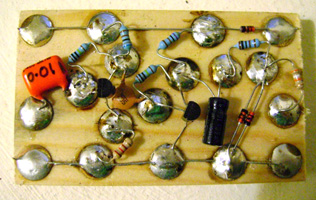
potential in a mains valve amp. In the finished board, below right, there is
an omition: the diodes aren't connected!
there is meant to be a joining wire that
connects the diodes. This joins R8
1K, R9 39K junction to the diodes. It's
a good idea to temporarily disconnect these
diodes during testing so that the clipping
action can be heard. The finished item should
be mounted inside a metal box which will
also house the battery. I've often seen
these built into M.T. tobacco tins.
|
|
|
|
|
|

|
|
|
Similar
Fuzz with Stain alterations
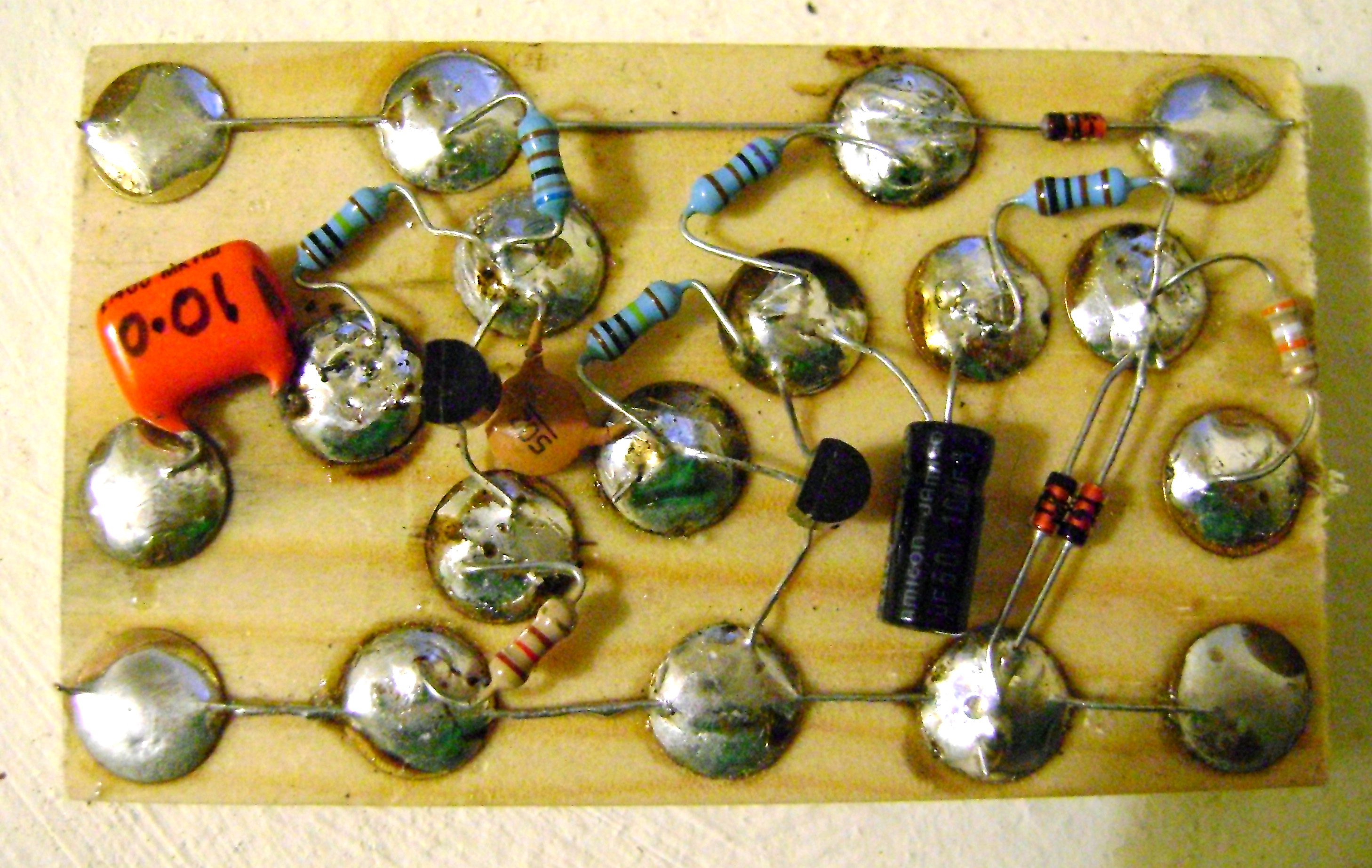
As
stated previously, I don't much like the
sound of the one in the photos above. Here
is a modified circuit that, in my opinion,
sounds a lot better. In the next pane is
the finished board, ready for installation
into a metal case which will also house
the connectors, switches and battery.
|
|
|
|
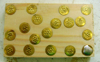
Arranged, are 18 drawing pins
on the wood: size 5/16ths X 1.5 X 3
inch.
|
|
The first 6 components
are soldered...
|
|
|
|
 ..and then the second transistor.
|
|
|
<< At this stage, the 'amplifier'
component arragement may be tested by connecting
a set of high impedance headphones between
ground/negative and output capacitor. Supply
is a 9 volt supply or battery, type PP3.
|
|
|
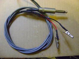
<< A guitar test lead with
a pair of crockadile clips soldered onto
the end instead of the usual jack output
connector plug. As shown above, it connects
between the 0.01 mfd input capacitor and
ground-line.
|
|
|