Aluminium Chassis Construction |
Building your own electonic equipment can be a means of obtaining stuff that isn't usually available and you've acquired a sufficient skill level you can design gear to your own specifications. Valves/tubes are highly desired for use in guitar amplifiers and equipment built using generic components will last and will probably always be repairable. There's a wrong and right way to do almost anything and if the right way is chosen from onset, you can build and own a perfectly functioning and smart piece of electronic equipment. However, start out by building something that looks crap and, although may work reasonably well, you probably won't want to use it.
Described here is the building of an aluminium chassis that became a signal generator, but a valve amplifier, mixer or similar audio or electronic device would proceed similarly. I learned my instrument building skills in the '70s whilst working for a small engineering company called Holdroman Engineering who provided equipment for the military. After leaving the job I decided to continue the craft as a highly satisfying hobby. |
|
Using metal-working tools and sheet aluminium can be dangerous: please be careful! |
 << Tools Required >>
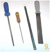
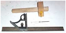
Mortise Gauge and Set Square Round and flat file, Abrafile and hacksaw blade,
and a
bradawl that was from a Christmas cracker and >>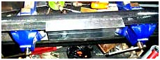 <<the most essential bit that is also expensive and takes up a lot
of space: two identical vices bolted onto a firm heavy bench with a pair
of angle irons held therein.
<<the most essential bit that is also expensive and takes up a lot
of space: two identical vices bolted onto a firm heavy bench with a pair
of angle irons held therein.
 Obtaining 18 swg is getting difficult but 20 swg is simply too thin for chassis
construction. Much of this material is sold for blocking up fireplaces, when installing
gas heaters. If you live in Hastings there's a shop called Cheshire's in Queens
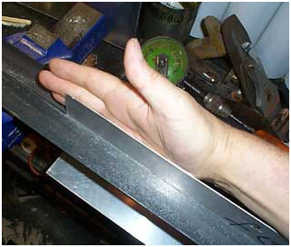
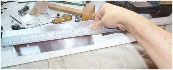
Road that sells it. To finish up with a tidy instrument all edges must be totally square.
Never assume that an alluminium sheet is: always check this by using a
known-good tool, as in this example.
Obtaining 18 swg is getting difficult but 20 swg is simply too thin for chassis
construction. Much of this material is sold for blocking up fireplaces, when installing
gas heaters. If you live in Hastings there's a shop called Cheshire's in Queens
Road that sells it. To finish up with a tidy instrument all edges must be totally square.
Never assume that an alluminium sheet is: always check this by using a
known-good tool, as in this example.
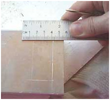
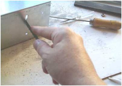
 Illustrated here is an edge that's not square and will have to be filed to a line.
Line is scribed using a bradawl.
Illustrated here is an edge that's not square and will have to be filed to a line.
Line is scribed using a bradawl.
Next,
>>  <<
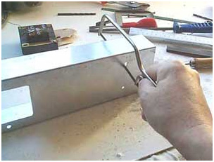
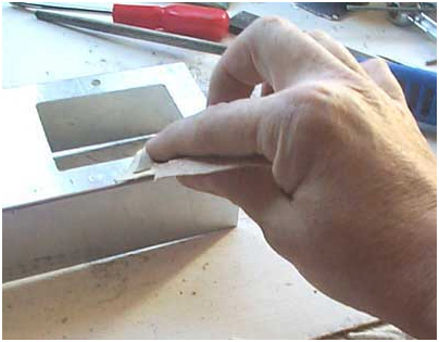
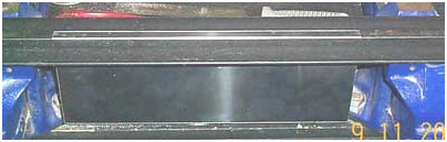
using a mortise gauge, score a line 5cm (about 2") from one edge and repeat this action on
the opposite edge. Feed it into the vices-held angle iron pairs up to the scored lines.
Make frequent checks for accuracy until the scored line exactly corresponds
with angle-iron edges, tightening the vices gradually as you proceed: mistakes
at this stage are unredeemable. Once straightness/squareness has be
ascertained, fully tighten the vices and get pushing/folding as illustrated.
<<
using a mortise gauge, score a line 5cm (about 2") from one edge and repeat this action on
the opposite edge. Feed it into the vices-held angle iron pairs up to the scored lines.
Make frequent checks for accuracy until the scored line exactly corresponds
with angle-iron edges, tightening the vices gradually as you proceed: mistakes
at this stage are unredeemable. Once straightness/squareness has be
ascertained, fully tighten the vices and get pushing/folding as illustrated.
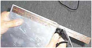
Nearly
there! Hence: don't rush it. 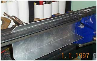
Complete the fold using a rubber or wood mallet. (Important: don't use a metal hammer!)
 <<
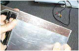
How it should be.
<<
How it should be.
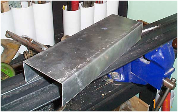
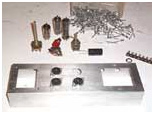
Do the same thing on the opposite edge and what you will have should look something like the above. Take measurements at this stage and the results should be no more than about 2.5mm out: your discretion. Inaccuracies in the front and rear drops could be filed to size, however. Next: make the holes and apertures that accommodate the components.
A typical valve equipment transformer (below)
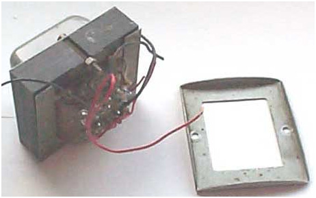 <<
In spite of it being hard-work, I always prefer to use a 'drop through' mains
transformer. It makes the finished item look as if it was done by someone who
knows what they're doing. If you have such, the only way of mounting it is as
dictated by the component design in any case: those intended to be mounted above chassis
only require two or four mounting holes and two gromitted holes for the connecting wires.
<<
In spite of it being hard-work, I always prefer to use a 'drop through' mains
transformer. It makes the finished item look as if it was done by someone who
knows what they're doing. If you have such, the only way of mounting it is as
dictated by the component design in any case: those intended to be mounted above chassis
only require two or four mounting holes and two gromitted holes for the connecting wires.
 <<
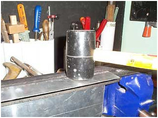
PWR (mains) transformer separated from its clamp. Use this clamp as a template
for cutting the transformer hole.
<<
PWR (mains) transformer separated from its clamp. Use this clamp as a template
for cutting the transformer hole.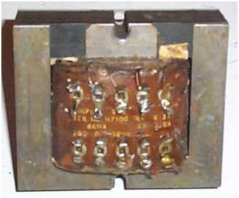
Close up details of transformer with clearly marked terminals. Another type may have wires hanging out which would make the winding identification task difficult, unless colour coded wires are used: seek advice from your nearest radio club because mis-wiring to the mains would be extremely dangerous.
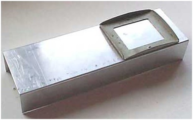 <<
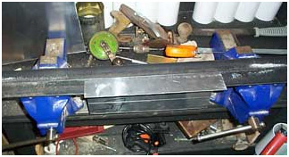
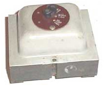
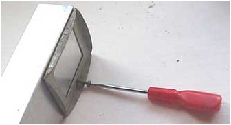
Clamp placed onto one end of chassis. This component is usually placed here
and rarely in the middle.
<<
Clamp placed onto one end of chassis. This component is usually placed here
and rarely in the middle.
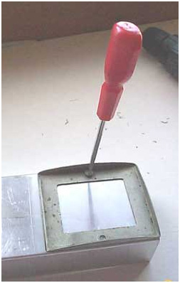
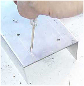
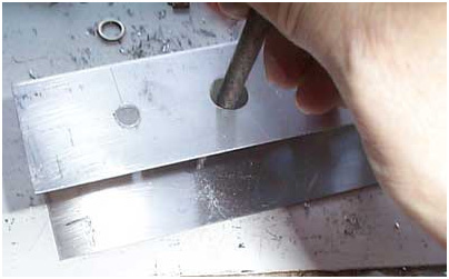
When working with steel (which we
are not)>>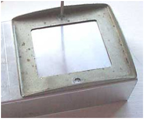 centre punches are used with a hammer: unnecessary with soft
metals like aluminium, the chassis risking distortion by such an impact.
Much better is to use the point of a bradawl, nail or similar.
Next, the holes are drilled.
centre punches are used with a hammer: unnecessary with soft
metals like aluminium, the chassis risking distortion by such an impact.
Much better is to use the point of a bradawl, nail or similar.
Next, the holes are drilled.
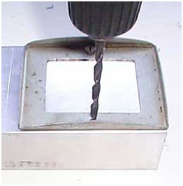 <<
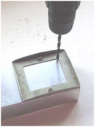
Like this! And This! >>
<<
Like this! And This! >>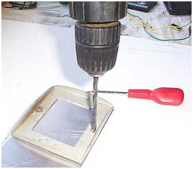
 <<
Once the holes are drilled, one of the transformer bolts (commonly 0BA) can be
inserted.....
<<
Once the holes are drilled, one of the transformer bolts (commonly 0BA) can be
inserted.....
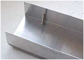
followed by the other one, and tightened >>
 <<
First hole to accommodate the
<<
First hole to accommodate the 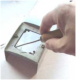 Abrafile. When the hole is of sufficient size
 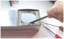 a hacksaw blade makes quicker progress. It's necessary to drill 'starter' holes at opposite corners
of the clamp. It helps to wrap a hacksaw blade with tape to form a makeshift
handle.
a hacksaw blade makes quicker progress. It's necessary to drill 'starter' holes at opposite corners
of the clamp. It helps to wrap a hacksaw blade with tape to form a makeshift
handle.
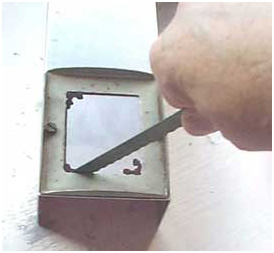 << Sawing continued.
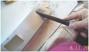
 << Filing.
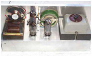
 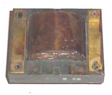 << Output transformers are mounted at the opposite end from PWR ones.
This is done to prevent magnetic interaction between the two components that
may result
in mains hum interference out of the speaker. This particular transformer
was a spare part for an obsolete (UK) 405 line telly: field deflection
output/matching.
It would be unusable for an audio output in an amplifier (unless the speaker it
fed was 64 ohms or so) although ideal for a high output signal generator.
<< Output transformers are mounted at the opposite end from PWR ones.
This is done to prevent magnetic interaction between the two components that
may result
in mains hum interference out of the speaker. This particular transformer
was a spare part for an obsolete (UK) 405 line telly: field deflection
output/matching.
It would be unusable for an audio output in an amplifier (unless the speaker it
fed was 64 ohms or so) although ideal for a high output signal generator.
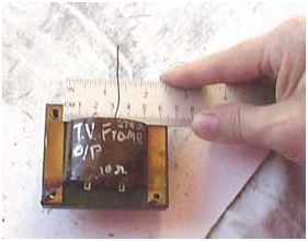
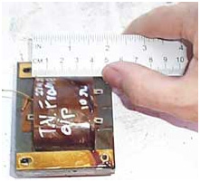
There wasn't a clamp with this transformer so taking measurements was the option. Once again, dropthrough, but accuracy only has to be to the nearest eighth of an inch.

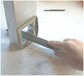
 << cut along the line.
Another way of sawing aperture>>
 if preferred,
using a Junior hacksaw: disconnect, feed into starter hole, reconnect.
if preferred,
using a Junior hacksaw: disconnect, feed into starter hole, reconnect.
A QMax chassis punch for 9BA valve
bases >> 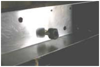 If you want your chassis punches to last, it's essential to grease the bolt
and both cutting surfaces. Maplin (I think) sells chassis punch sets but it's
also possible to drill a hole and file it to fit a valve holder size.
If you want your chassis punches to last, it's essential to grease the bolt
and both cutting surfaces. Maplin (I think) sells chassis punch sets but it's
also possible to drill a hole and file it to fit a valve holder size.
|
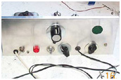
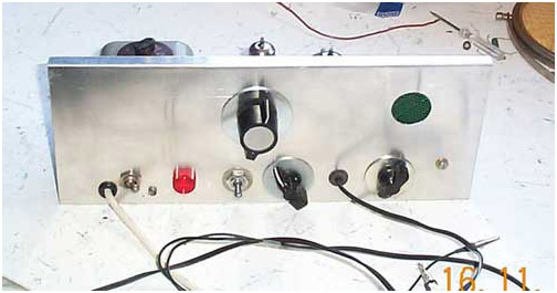
Holes to fit potentiometers, switches and lamps are best drilled using a guide line that is approximately half way between the top and bottom of the panel. This may be done using a mortice guage. Next, scribe drilling reference points starting 2.54 cm (1 inch) from the left hand or right hand edge. A good distance for each hole to be drilled is 1.5" apart. (about 3.8cm) This distance is a good choice because if the control knobs are too bunched together, any inaccuaracies in your measurements might unnecessarilly spoil the appearance. You could go as far as 2" (5.08) but you may be short of places into which the controls are inserted. I always make holes throughout the entire front panel from end to end in the event that you would wish to make improvements at a later stage, such as additional potentiometers, rotary switches and similar. Unused holes can be blind-grommit obscured or covered by an additional panel. |
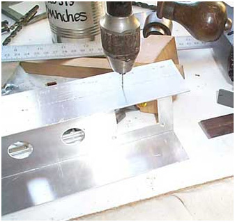 Start with a 1 or 2 mm bit as a pilot and progress gradually up to the necessary size.
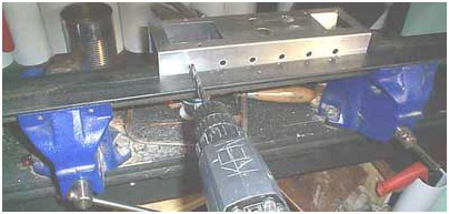
|
Best position for the potentiometer, switch and pilot lamp holes is half-way up the chassis front panel. Get a mortise gauge and score a line half way between top and bottom. Repeat this action from the opposite edge and you will end up with two lines and make a dent between these 1" from one end. Typical spacing is 1.5" between one shaft and another, so dent (using bradawl) a drill mark/guide. Drill all holes with a 1 - 2 mm bit, progressing to larger sizes until three eighths typically, or whatever the device size fixing hole should be. |
 << Aluminium oxide paper to de-burr.
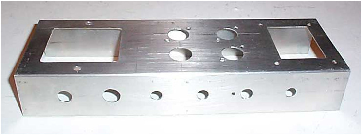
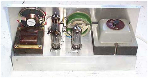
Finished aluminium chassis ready........ 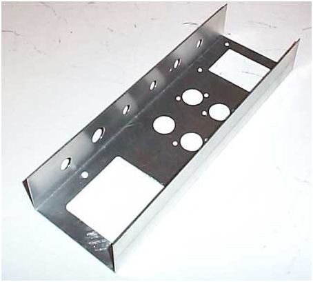
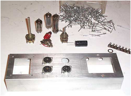 ...for component installation.
|
Described so far is a means of building a chassis from aluminium. Wiring is presented as an example of how a project may proceed but this may vary considerably according to differing circuit specifications, and the soldering/ wiring may be viewed as a separate skill, possibly needing to be learned by any prospective constructor. The usual precautions of electrical safety should be adhered to and the appropriate advice sought via qualified persons. |
Heater circuit wiring
>>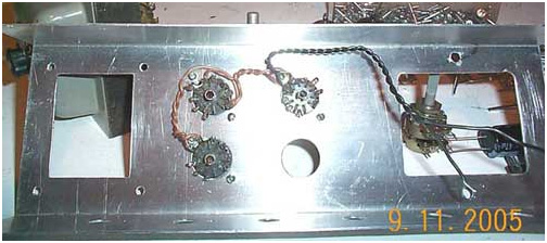
 O/P transformer and GRND bus.
Ticcie likes to help >> 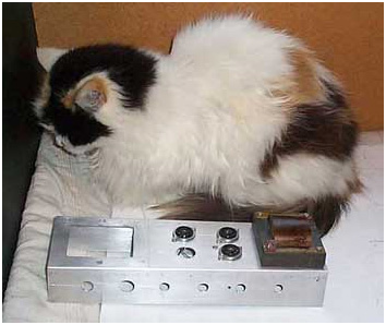
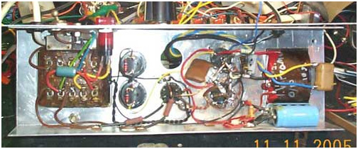 <
Near complete instrument, chassis underview. Front
panel fabrication >
<
Near complete instrument, chassis underview. Front
panel fabrication >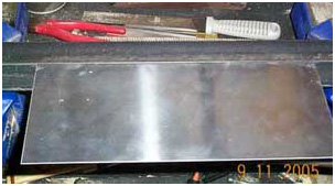
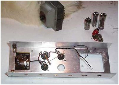
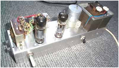
Working instrument chassis >
 < Initial stage of working instrument.
|
The above instrument is for electronic investigation and testing purposes and wouldn't find a use in most peoples' homes. The following two illustrations are those of something more useful in a domestic environment: an audio amplifier. Once enclosed, it can be used for music/sound reproduction purposes. Presented for example only, it would be unwise to attempt using it in this unprotected state for risk of electrical shock hazzard. |
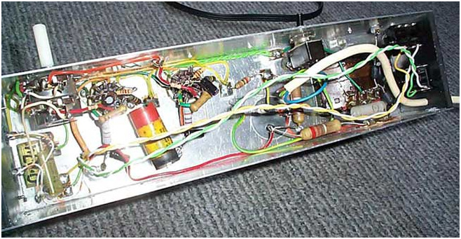
Underside view. Most of the components were stripped out of a radiogram, the cabinet of which was well beyond redemption, being cracked and rotten.